The multi band communication system lab comprises of RF and Microwave laboratory and communication Systems Laboratory.
The focus of the RF and Microwave laboratory is the development and use for scientific studies of the microwave frequencies. This lab is adequately equipped with microwave benches at J-Band and X-Band, which includes klystron tubes, Gunn diodes, Klystron power supplies, modulators, directional couplers, various power energy and VSWR meters to carry out basic microwave measurements, such as impedance, power, frequency, VSWR etc., using waveguide technology. The major areas of research involve simulation, analysis, design and development of microwave circuits, components and sub-systems for RF, microwave, millimetre wave applications. Students learn to simulate and design RF and Microwave circuits, then fabricate, measure, and evaluate their prototype using modern laboratory instruments, which are similar to instruments presently being used by engineers in industry. Students use CST Studio Suite to simulate, verify, and optimize their design. The lab also provides the necessary equipment for the students to perform their projects.
The communication Systems Laboratory intends to cover the basic understanding of functionalities of various block-sets involved in communication system. It involves system design and simulation exercises using MATLAB and Simulink and experiments based on HW boards. Students are introduced to the functioning of modern communication systems and its performance in the presence of noise.
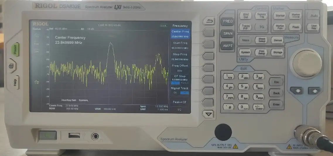
The spectrum analyzer is used for analyzing waves in frequency domain. Basically, it displays the energy distribution of a signal on its CRT screen. Here, x-axis represents frequency and y-axis represents the amplitude. A spectrum analyzer measures the magnitude of an input signal versus its frequency over the full frequency range of the instrument to determine the power of signals. Spectrum analyzers enable tests like noise figure and signal-to-noise ratio (SNR) to characterize the performance of a device and its contribution to overall system performance.
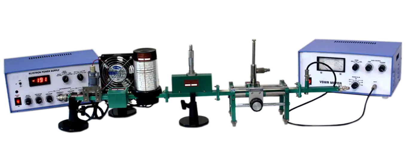
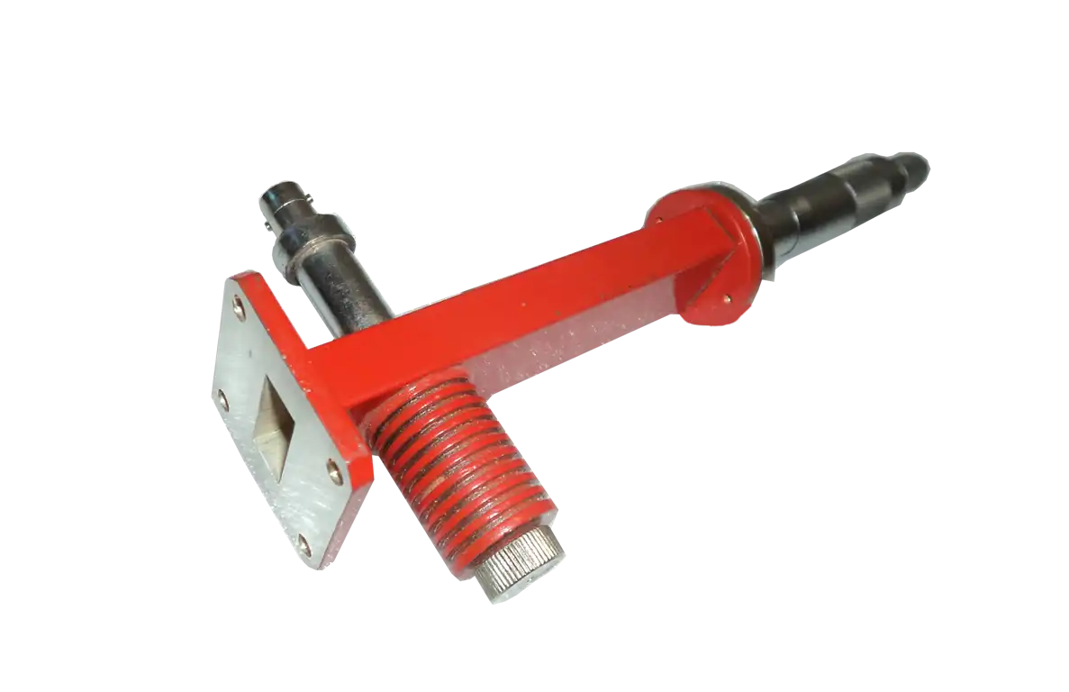
A microwave test bench is a piece of equipment that is useful in testing the performance of microwave components and circuits. Microwave test bench components typically include a power source, a load, and a device under test (DUT). The power source provides the energy to generate the microwaves, while the load absorbs the microwaves to dissipate the energy. The waveguide helps guide the microwaves from the start to the load.
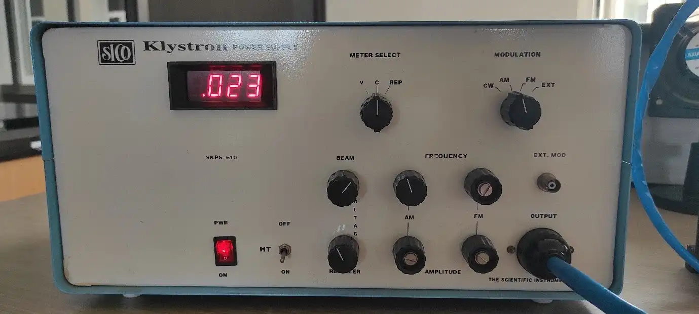
Klystron Power Supply generates voltages required for driving the reflex Klystron tube, It is stable, regulated and short circuit protected power supply. It has built on facility of square wave and saw tooth generators for amplitude and frequency modulation. The beam voltage ranges from 200V to 450V with maximum beam current of 50mA. The provision is given to vary repeller voltage continuously from-270V DC to -10V.
For the generation and amplification of Microwaves, there is a need of some special tubes called as Microwave tubes. Of them all, Klystron is an important one.The essential elements of Klystron are electron beams and cavity resonators. Electron beams are produced from a source and the cavity klystrons are employed to amplify the signals. A collector is present at the end to collect the electrons.
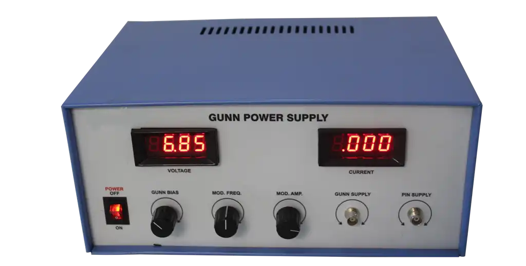
Gunn Power Supply comprises of an electronically regulated power supply and a square wave generator designed to operate the Gunn oscillator and PIN Modulator. The Supply Voltage ranges from 0 to 12V with a maximum current of 1A.
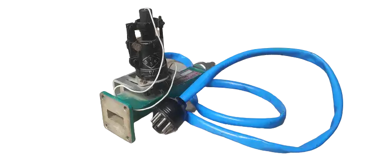
Gunn oscillator uti1izes Gunn diode which works on the principle that when a DC voltage is applied across a sample of n-type Gallium Arsenide; the current oscillates at microwave frequencies. This does not need high voltage as it is necessary for Klystrons and therefore solid state oscillators are now finding wide applications. Normally, they are capable of delivering 0.5 watt at 10GHz, but as the frequency of operation is increased the microwave output power gets considerably reduced.
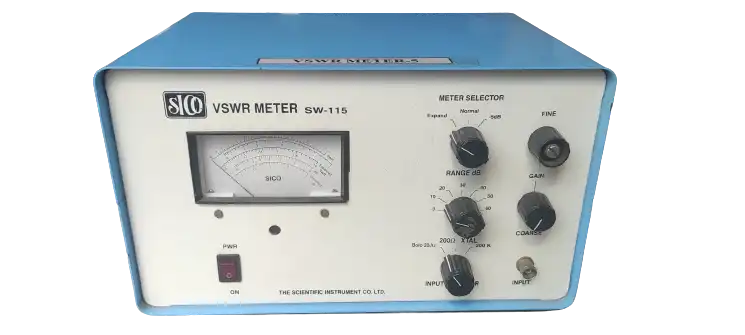
Direct-reading VSWR meter is a low-noise tuned amplifier voltmeter calibrated in db and VSWR for use with square law detectors. A typical SWR meter has a standard tuned frequency of 100-Hz, which is of course adjustable over a range of about 5 to 10 per cent, for exact matching in the source modulation frequency. Clearly the source of power to be used while using SWR meter must be giving us a 1000-Hz square wave modulated output. The band width facilitates single frequency measurements by reducing noise while the widest setting accommodates a sweep rate fast enough for oscilloscope presentation.

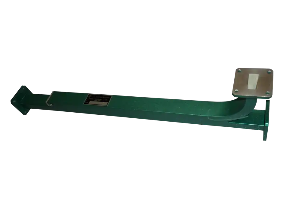
An E plane tee is a waveguide tee junction in which the axis of the side arm is parallel to the electric field. Two arms of the Tee junction are collinear arms. Signal entering at one port is divided among other two ports in such a way that the signals are out of phase with each other. The output of the E-plane will be the difference between input signals. The side arm of E-plane Tee is also known as difference arm.
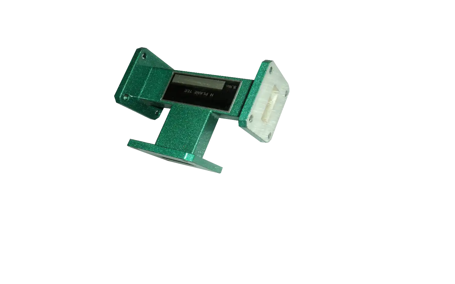
In H Plane Tee, the side arm or H arm is parallel to the magnetic field. The signal fed to one of the ports will be divided between the other two ports and the signals will be in phase. The output of the H Plane Tee is the sum of input signals
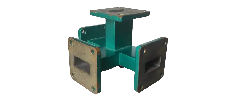
The magic tee is a combination of E and H plane tees. Arm 3 forms an H-plane tee with arms 1 and 2. Arm 4 forms an E-plane tee with arms 1 and 2. Arms 1 and 2 are sometimes called the side or collinear arms. Port 3 is called the H-plane port, and is also called the Σ port, sum port or the P-port (for parallel). Port 4 is the E-plane port, and is also called the Δ port, difference port, or S-port (for series). There is no one single established convention regarding the numbering of the ports.
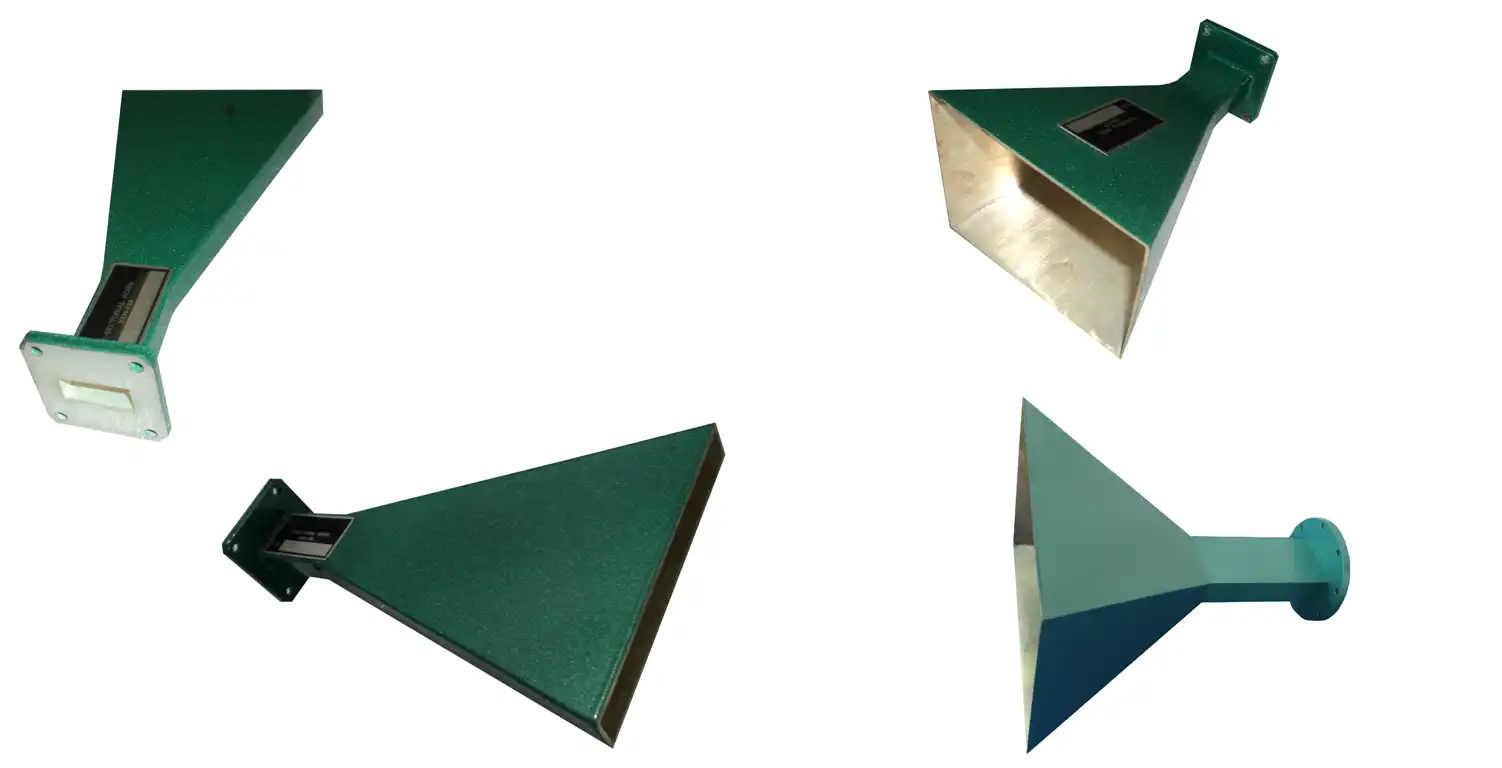
Horns are open ended Waveguide in which open end is flared so that it looks like horn. Commonly used horn antennas are pyramidal horn, E Sectorial, H Sectorial Horn and the pick up horns. These horns are used to determine the gain of the antenna under test by convectional substitution method and are also used as general purpose radiators. They are also used as reference sources in dual channel antenna test receivers and can be used as pick up horns for radiation monitoring.
It is a four port waveguide junction consisting of primary main wavelength and a secondary auxiliary waveguide. They can Sample a small amount of microwave power for measurement purpose. They are designed to measure incident and reflected power, SWR Values, provide a signal path to a receiver or perform other desirable operations. The coupling is done through holes on the broad side of the waveguide. The diameter in the no of holes in a row and the number of rows vary according to coupling sector required. Scientific Microwave offers 3dB, 10dB, and 20dB couplers to its customers with minimum VSWR.
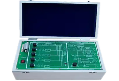
Eleven usable 64 kbps channels
User definable frame marker (two alternating 8-bit markers - can be set to CCITT compatible)
On-board two digitised voice channels, one 8-bit data channel and several user-expansion channels
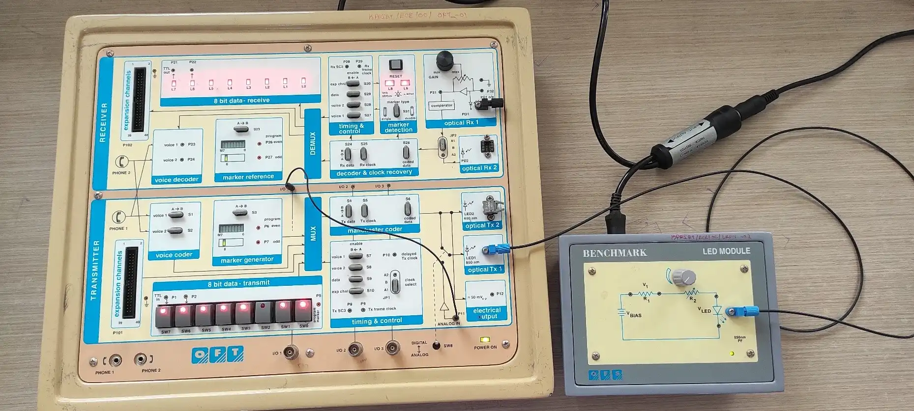
Demonstrates fully operational integrated voice/data fibre-optic communication link
RS - 232C communications module optional - demonstrates computer communications over fibre
Time Division Multiplexing of voice, data & user-defined data streams
Modular design enables configuration with user-defined modules
Wide scope for experimentation through use of external circuitry interfaced to kit
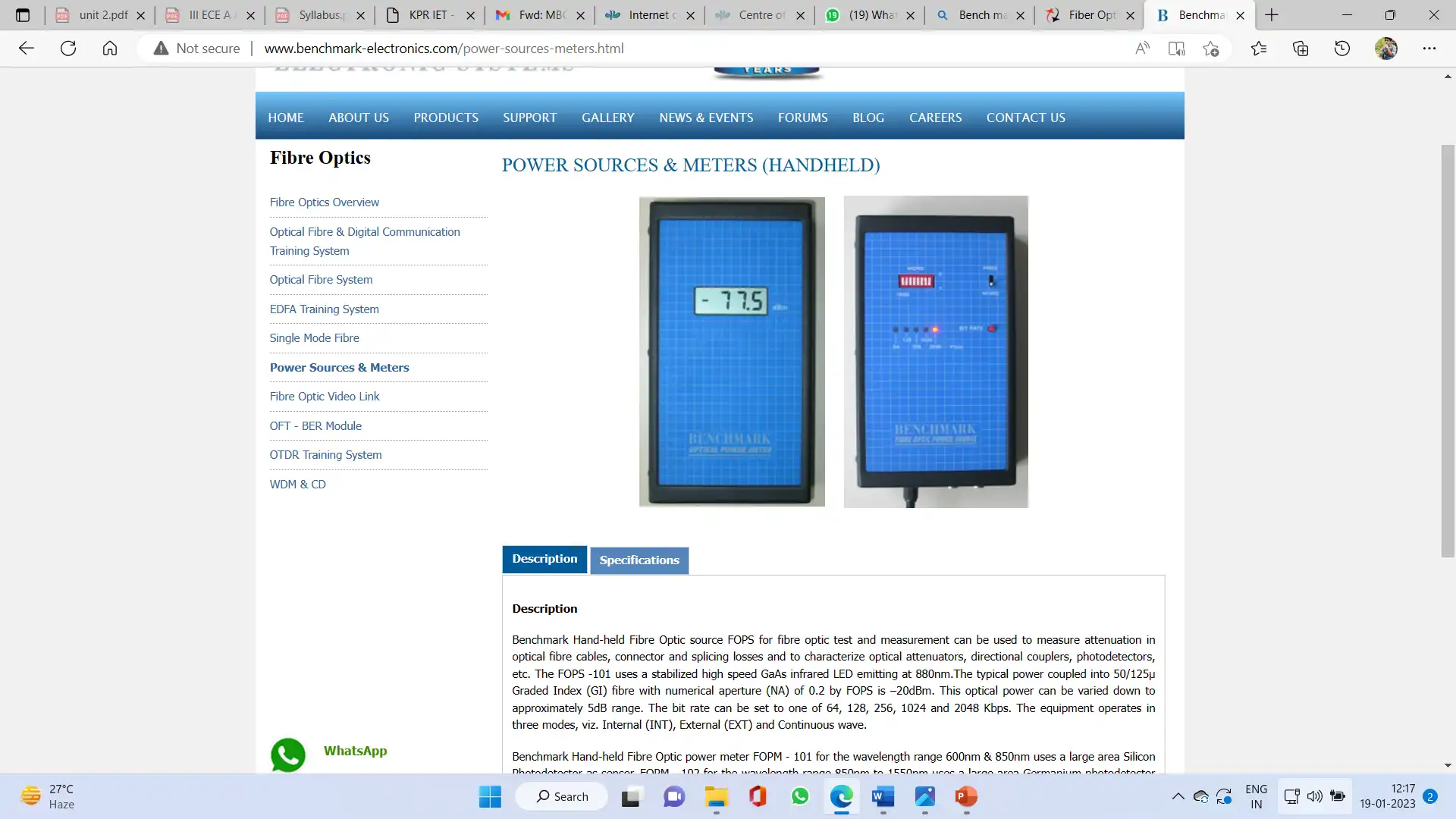
Benchmark Hand-held Fibre Optic source FOPS for fibre optic test and measurement can be used to measure attenuation in optical fibre cables, connector and splicing losses and to characterize optical attenuators, directional couplers, photodetectors, etc. The FOPS -101 uses a stabilized high speed GaAs infrared LED emitting at 880nm.The typical power coupled into 50/125μ Graded Index (GI) fibre with numerical aperture (NA) of 0.2 by FOPS is –20dBm. This optical power can be varied down to approximately 5dB range. The bit rate can be set to one of 64, 128, 256, 1024 and 2048 Kbps. The equipment operates in three modes, viz. Internal (INT), External (EXT) and Continuous wave.
Benchmark Hand-held Fibre Optic power meter FOPM - 101 for the wavelength range 600nm & 850nm uses a large area Silicon Photodetector as sensor. FOPM - 102 for the wavelength range 850nm to 1550nm uses a large area Germanium photodetector as sensor. The FOPM - 101 power meter has been calibrated at 850nm and FOPM - 102 power meter has been calibrated for 850nm, 1300nm and 1550nm and the calibration wavelength is switch selectable. It can measure optical power from –60dBm (1nW) to +3 dBm (2mW). A three and half digit LCD display provides a direct readout in dBm, with a resolution of 0.1 dB. The power meter is provided with universal adaptor with ST interface. It allows the measurement of optical power even at high bit rates as it reads the average power.
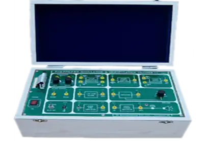
PAM- PPM- PWM is the basic pulse modulation techniques. This trainer provides complete setup to the students for performing Experiments on these techniques. They can study Sampling, Pulse Modulation &Signal reconstruction process. Separate circuits are provided for each Techniques.
Crystal based clock generator
On-board synchronized sine wave generator (250Hz, 500 Hz,1KHz, 2KHz)
On-board DC voltage for receiver synchronization
Four channel Time Division Multiplexing & Demultiplexing
Three wire, Two wire and single wire transmission system
On-board PLL for clock Recovery
Comparator for receiver channel synchronization
Fourth order butter worth Low pass filter
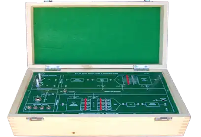
In-built sine wave generator
Test points to study different waveforms
In-built DC Power supply