The laboratory is mainly used for instructional laboratory courses and is well equipped with sufficient number of electronic test benches each consisting of CRO, Digital Storage Oscilloscope, Function Generator, Digital Multimeter, Desktop computer, etc. used in design and implementation of automation, control and instrumentation circuits. This laboratory is also used for research work in the areas of automation, control and instrumentation.
To provide adequate knowledge on analysis and design of control system along with basics of instrumentation.
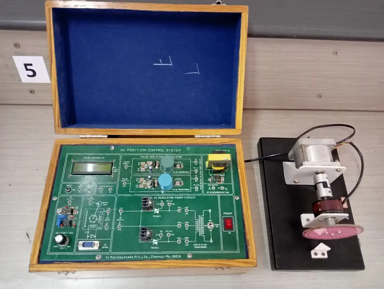
Servo systems have wide applications in automated industries, spacecraft's, missiles, robots etc... An AC servomotor is a two phase AC motor. It consists of a reference winding and control winding which are placed 90 degree mechanically in space, and supplied with voltages phase shifted by 90 degree. The torque produced in the motor is controlled by adjusting the control winding voltage. In AC position control system, AC servomotor is controlled in closed loop mode, by using either position feedback or velocity feedback or the combination of both.
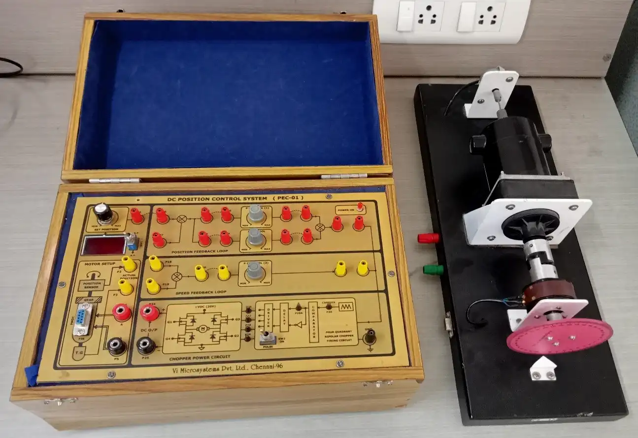
In modern control terminology the term “Servomechanism” is restricted to feedback control systems in which controlled variable is mechanical position. In its simplest form, the output (controlled) and derived (reference) position and are respectively measured and compared by a potentiometer pair whose output voltage is proportional to the error in angular position. The error voltage is simplified and applied to servomotor which positions the load and output pot such that the error is reduced to zero. The position control systems have innumerable applications, namely, Machine tool position control, constant tension control of sheet rolls in paper mills, Radar tracking systems, Roll stabilization of ships, Positioning of heavy guns on the tanks for defence application etc.
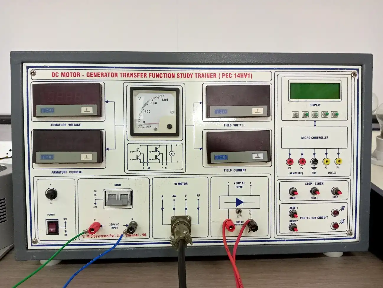
The speed of DC motor is directly proportional to armature voltage and inversely proportional to flux in field winding. In armature controlled DC motor the desired speed is obtained by varying the armature voltage. This speed control system is an electro-mechanical control system. We will discuss transfer function of armature controlled dc motor.
The electrical system consists of the armature and the field circuit but for analysis purpose, only the armature circuit is considered because the field is excited by a constant voltage.
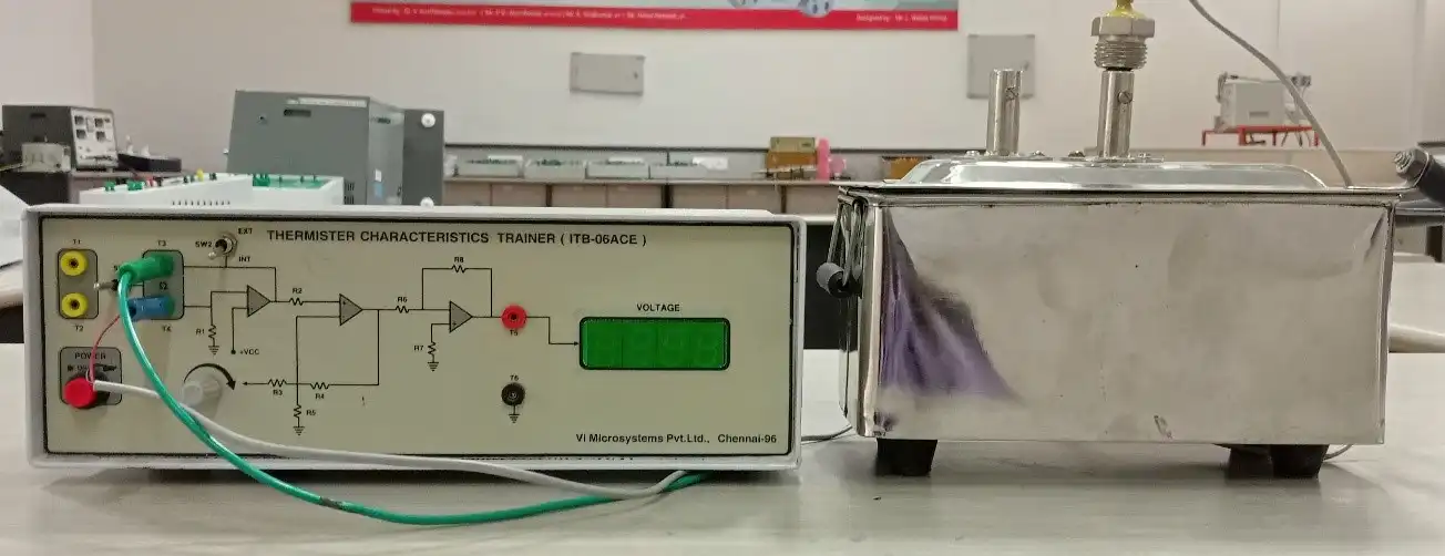
A water bath is a lab constant temperature equipment, providing heat source for varieties of devices that need heating. The circulating water bath is used to keep water at a constant temperature for incubating samples in a laboratory.
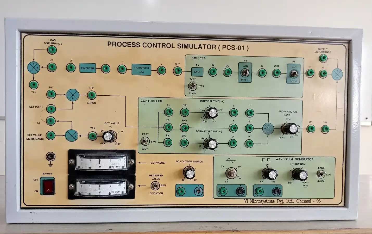
The process control simulator is a special purpose analog simulator with operational amplifiers The simulator permits a detailed analysis of the first order, second order and third order systems and the application of proportional, integral and derivative control to the improvement of their performance. The simulator may be used at high speed for oscilloscope observation or at a low speed for meter observation.
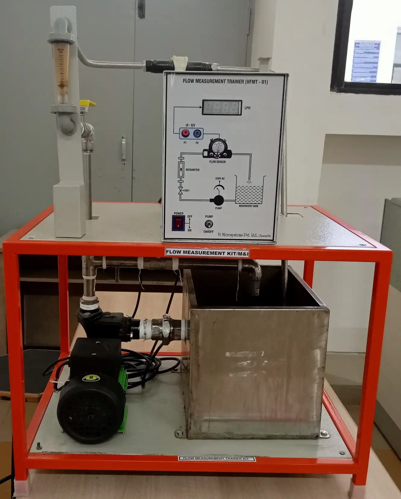
A pump is used to transport the water in a close circuit where the flow meters can be installed in two measuring positions: vertical or horizontal. A valve is used to adjust the flow rate.
The trainer is equipped with a high precision magnetic induction flow meter for reference measurement and for flow meters calibration, with two two-tube manometers and a differential pressure transmitter for measuring the pressure drop on the flow meters.
A voltage source powers is available for the supply of some optional flow meters.
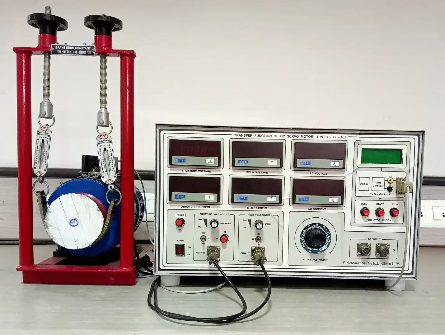
The transfer function is defined as the ratio of Laplace transform of the output variable to the Laplace transform of input variable. The DC motor converts electrical energy into mechanical energy. The electrical energy supplied at the armature terminals converted into controlled mechanical energy.
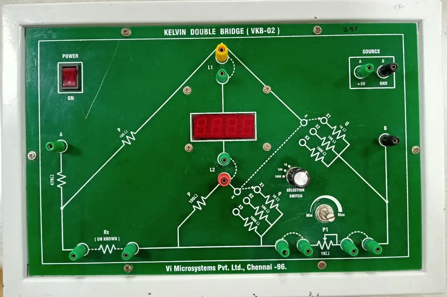
A bridge is an electrical circuit that consists of three branches that are connected at a common point and the intermediate bridging which is present can be adjustable. They are mainly used in an electrical Laboratory for measuring various parameters and in application like filtering, linear and nonlinear, etc. Bridges are classified into two types they are, DC bridges like Wheatstone Bridge, Kelvin Double Bridge, Mega Ohm Bridge and AC bridges like Inductance, Capacitance, Frequency. For measuring a small value of resistance like 1 ohm, we can either use an ohmmeter or a Wheatstone bridge, but in a case where the resistance value is less than 1 ohm, it will be difficult to measure. Hence, we shunt a lower value of the unknown resistors, 2 precision resistors, and a high current ammeter to form four-terminal resistors, where the current flows through the circuit, then the voltage drop across the resistors can be measured using a galvanometer, which together is a four-terminal resistor called kelvin bridge.
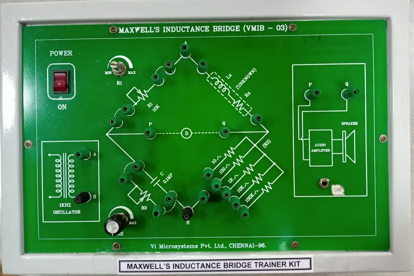
A Maxwell Inductance Capacitance Bridge (known as a Maxwell Bridge) is a modified version of a Wheatstone bridge which is used to measure the self-inductance of a circuit. A Maxwell bridge uses the null deflection method (also known as the “bridge method”) to calculate an unknown inductance in a circuit. When the calibrated components are a parallel capacitor and resistor, the bridge is known as a Maxwell-Wien bridge.
The working principle is that the positive phase angle of an inductive impedance can be compensated by the negative phase angle of a capacitive impedance when put in the opposite arm and the circuit is at resonance (i.e., no potential difference across the detector and hence no current flowing through it). The unknown inductance then becomes known in terms of this capacitance.
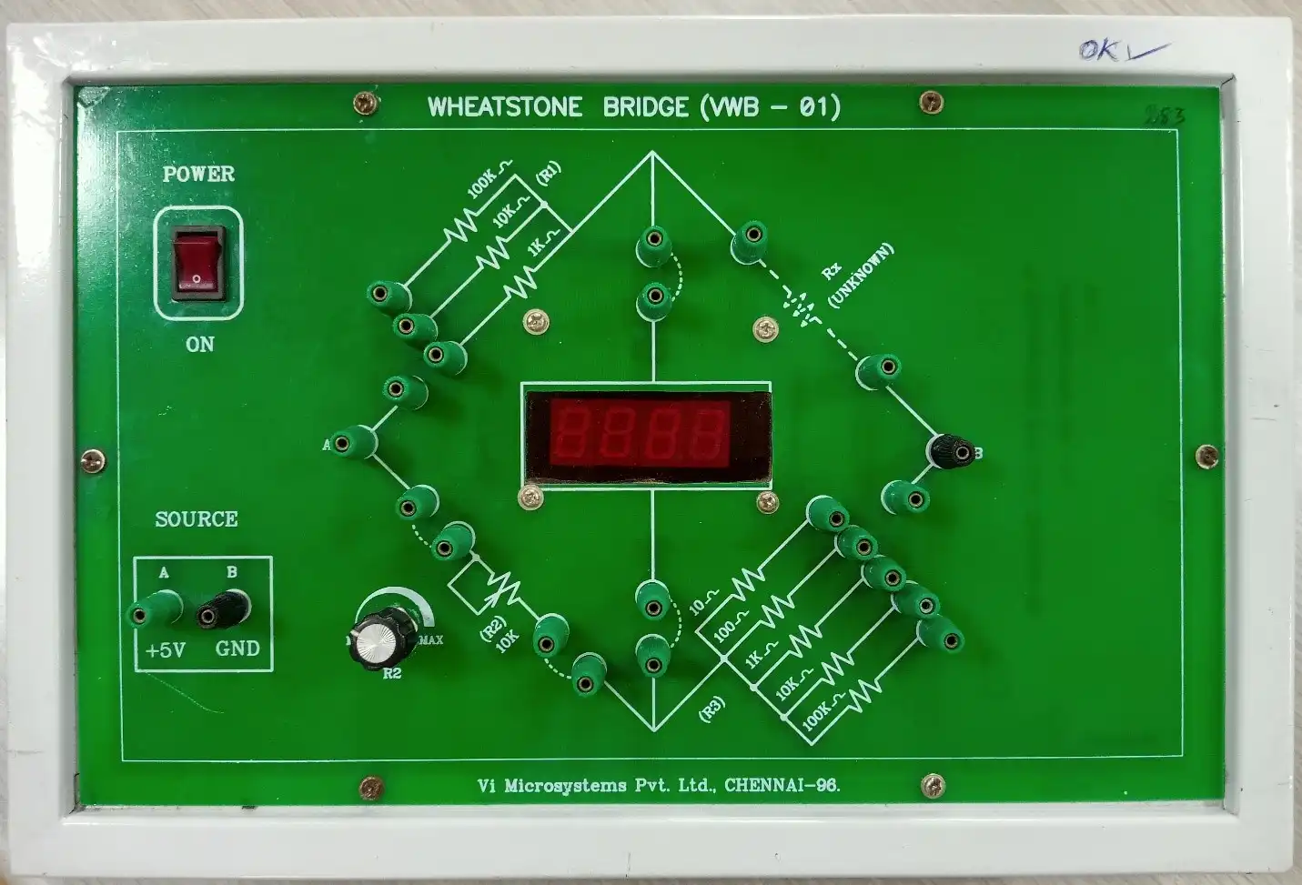
In the experiment, we measure resistance of the wires that 1-meter length but they are different cross-sectional area. In addition, the resistance of wires made of different materials with the same cross-sectional area and length will be examined. As a result of these measurements, the resistance of a wire and its dependence will be reinforced. In the second part of the experiment we make Wheatstone bridge experiment. The circuit known as a Wheatstone bridge is most commonly used to determine the value of an unknown resistance to an electrical current.
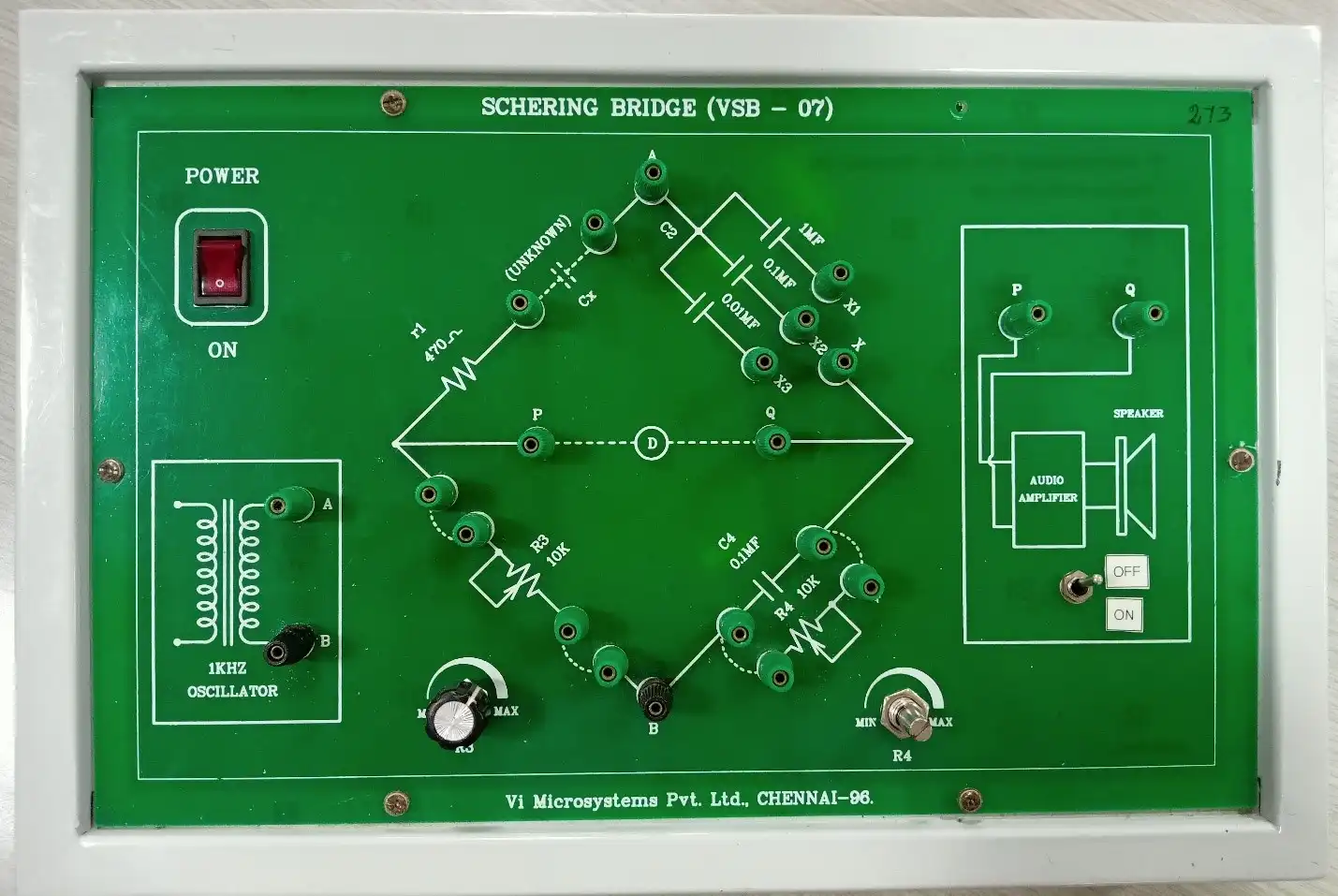
The Schering bridge is one type of AC bridge, which is used to measure the unknown capacitance, relative permeability, dissipation factor, and dielectric loss of a capacitor. The high voltage in this bridge is obtained by using the step-up transformer. The main objective of this bridge is to find capacitance value. The main apparatus required for connection are trainer kit, decade capacitance box, multimeter, CRO, and patch chords.