The Electronic devices and circuits provide the basic knowledge over the construction and functionality of the basic electronic devices such as diodes and transistors. It also provides the information about the uncontrollable and controllable electronic switches and the flow of current through these switches in different biasing conditions. This lab is intended to describe the different configurations and modes of controllable switches and how these electronic devices can be configured to work as rectifiers, clippers, clampers, oscillators, and amplifiers.
To produce professionally competent Electronics and Communication Engineers capable of effectively and efficiently addressing the technical challenges with social responsibility
The mission of the Department is to provide an academic environment that will ensure high quality education, training, and research by keeping the students abreast of latest developments in the field of Electronics and Communication Engineering aimed at promoting employability, leadership qualities with humanity, ethics, research aptitude and team spirit
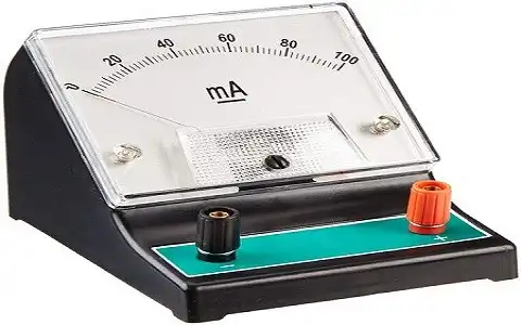
Ammeter, instrument for measuring either direct (DC) or alternating (AC) electric current, in amperes. An ammeter can measure a wide range of current values because at high values only a small portion of the current is directed through the meter mechanism; a shunt in parallel with the meter carries the major portion. In circuit diagrams, the symbol for an ammeter is a circle with a capital A inside. Ammeters vary in their operating principles and accuracies. The D'Arsonval-movement ammeter measures direct current flowing through a coil suspended between the poles of a magnet with accuracies of from 0.1 to 2.0 percent. The electrodynamic ammeter uses a moving coil rotating in the field produced by a fixed coil. It measures direct and alternating current (by using a rectifier to convert the AC to DC) with accuracies of 0.1 to 0.25 percent. In the thermal (or hot-wire) ammeter, used primarily to measure AC with accuracies of 0.5 to 3 percent, the measured current heats a piece of wire, and the current is indicated by how much the wire expands. Different range of ammeters are available from micro amperes to amperes in the laboratory.
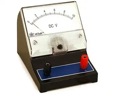
The instrument which measures the voltage or potential difference in volts is known as the voltmeter. It works on the principle that the torque is generated by the current which induces because of measurand voltage, and this torque deflects the pointer of the instrument. The deflection of the pointer is directly proportional to the potential difference between the points. The voltmeter is always connected in parallel with the circuit. Different ranges of voltmeters from millivolts to volts are available in the laboratory.
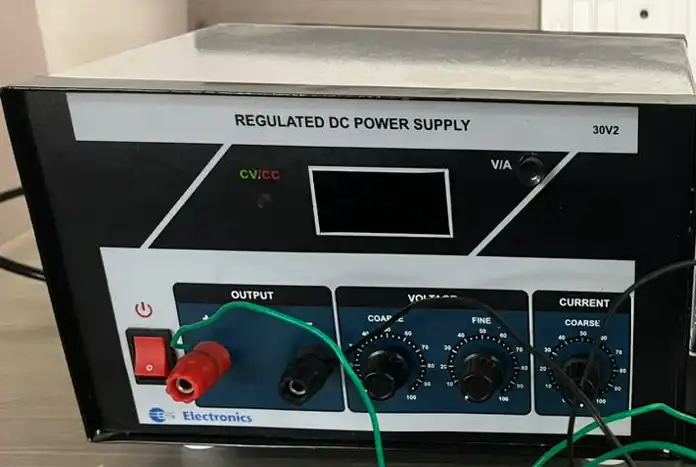
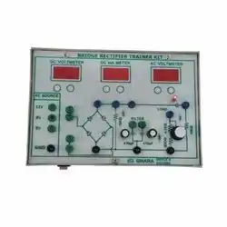
A regulated power supply is an embedded circuit; it converts unregulated AC (alternating current) into a constant DC. With the help of a rectifier, it converts AC supply into DC. Its function is to supply a stable voltage (or less often current), to a circuit or device that must be operated within certain power supply limits. The output from the regulated power supply may be alternating or unidirectional but is nearly always DC (direct current). The type of stabilization used may be restricted to ensuring that the output remains within certain limits under various load conditions, or it may also include compensation for variations in its own supply source. A DC power supply single channel is a power supply that provides a single, regulated DC voltage output. The output voltage is set using a potentiometer, and a fuse limits the current. The power supply helps power electronic devices that require a stable DC voltage, such as computers, stereos, and TVs.
Dual Output DC Regulated Power Supply are constant Voltage & Current limit type supplies, have high regulation for Load & line Voltage variation. The supply can be use in independent & current tracking made. The supply are protected against short circuit & over load.
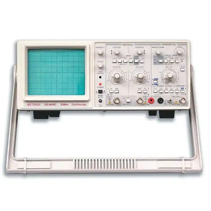
A Cathode Ray Oscilloscope (CRO) is an instrument generally used in a laboratory to display, measure, and analyze various waveforms of electrical circuits. A cathode ray oscilloscope is a very fast X-Y plotter that can display an input signal versus time or another signal. Cathode ray oscilloscopes use luminous spots which are produced by striking the beam of electrons and this luminous spot moves in response variation in the input quantity. At this moment one question must be arise in our mind that why we are using only an electron beam? The reason behind this is low effects of beam of electrons that can be used for following the changes in the instantaneous values of rapidly changing input quantity. The general forms of cathode ray oscilloscope operate on voltages. So the input quantity that we have talked above is voltage. Nowadays, with the help of transducers it is possible to convert various physical quantities like current, pressure, acceleration etc. to voltage thus it enables us to have a visual representation of these various quantities on cathode ray oscilloscope. Now let us look at the constructional details of the cathode ray oscilloscope.
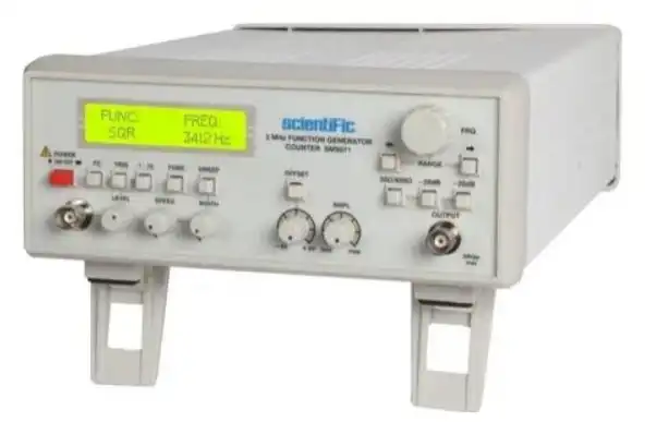
A function generator is a piece of electronic test instrument used to generate and deliver standard waveforms, typically sine and square waves, to a device under test. It can be used to test a design or confirm that a piece of electronic equipment is working as intended.
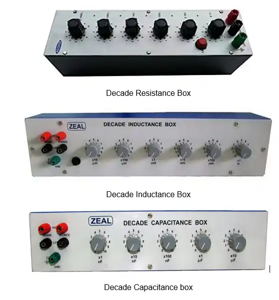
A decade box is a piece of test equipment that can be used during prototyping of electronic circuits to substitute the interchanging of different values of certain passive components with a single variable output. Decade boxes are made for resistance, capacitance, and inductance, the values of which can be adjusted incrementally by the turning of a knob or switch, with the contacts of the switch moving along a series of the respective components. The interface for these devices usually consists of dials or adjustable tape counters, and they are operated in-circuit and without any external power source.
The output characteristics of the common-emitter configuration are transistor usage, output voltage and current. The transistor is used to amplify the input signal and the output voltage and current are determined by the transistor's characteristics. The transistor's characteristics are determined by the transistor's construction and the type of semiconductor material used. There are two types of output characteristics, linear and nonlinear.
Linear Output: Linear output characteristics are those where the transistor's output voltage is proportional to the transistor's input voltage.
Non-linear output: Nonlinear output characteristics are those where the transistor's output volt The output characteristics in a transistor are important because transistor usage is based on the transistor's output characteristics. There are three transistor configurations which are common emitter, common base, and common collector. The transistor's output characteristics are different for each configuration. The transistor's output characteristics will determine the transistor's function and how it can be used within a circuit. The transistor's output characteristics will also determine the transistor's operating point. The transistor's operating point is the voltage or current at which the transistor will be turned on or off. The transistor's operating point is important because it determines the transistor's power dissipation. The output characteristics in a transistor are also important because they determine the transistor's gain. The transistor's gain is the ratio of the output voltage to the input voltage. The transistor's gain is important because it determines the transistor's amplification factor. The transistor's output characteristics are also important because they determine the transistor's transistor action. The transistor's transistor action is the transistor's ability to switch between two states.
JFET or Junction field effect transistor is a 3 terminal device in which the voltage is applied at 1 terminal to control the output current. These are devices with three terminals which are source, gate, and drain. Only the majority of charge carriers are responsible for the current flow, therefore JFET are unidirectional. When no voltage is applied across the source and gate, the channel is a smooth path for the electrons to flow through, JFET is in the ohmic region, when the Gate voltage is negative it is in Pinch off region and when the Gate voltage is more than threshold voltage it is in Saturation region when the Gate voltage is very high JFET breaks down. Characteristics of JFET for which it is mostly used are fast switching, and for low frequency operation, source and drain can be interchanged. In JFET, gate voltage controls the current. They have one majority carrier which is responsible for conduction current. JFET are small in size and have high input impedance.
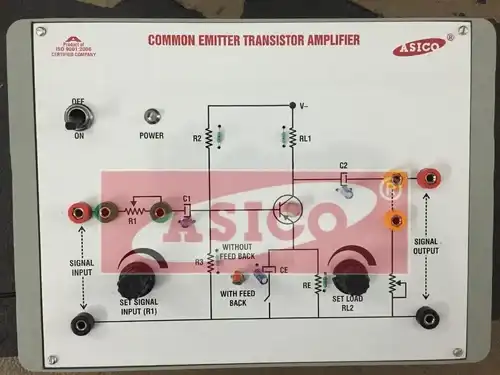
The voltage gain of a CE amplifier varies with signal frequency. It is because the reactance of the capacitors in the circuit changes with signal frequency and hence affects the output voltage. The curve drawn between voltage gain and the signal frequency of an amplifier is known as frequency response. The below figure shows the frequency response of a typical CE amplifier. At Low Frequencies (< FL) The reactance of coupling capacitor is relatively high and hence very small part of the signal will pass from the amplifier stage to the load. Moreover, CE cannot shunt the RE effectively because of its large reactance at low frequencies. These two factors cause a drops off of voltage gain at low frequencies. At High Frequencies (> FH) The reactance of coupling capacitor is very small and it behaves as a short circuit. This increases the loading effect of the amplifier stage and serves to reduce the voltage gain. Moreover, at high frequencies, the capacitive reactance of base-emitters junction is low which increases the base current. This frequency reduces the current amplification factor β. Due to these two reasons, the voltage gain drops off at a high frequency.
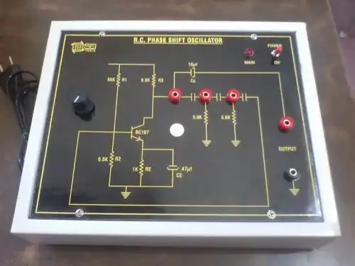
The oscillator circuit that produces a sine wave using a phase-shift network is called as a Phase-shift oscillator circuit. The phase-shift oscillator circuit consists of a single transistor amplifier section and a RC phase-shift network. The phase shift network in this circuit, consists of three RC sections. At the resonant frequency fo, the phase shift in each RC section is 60o so that the total phase shift produced by RC network is 180o.
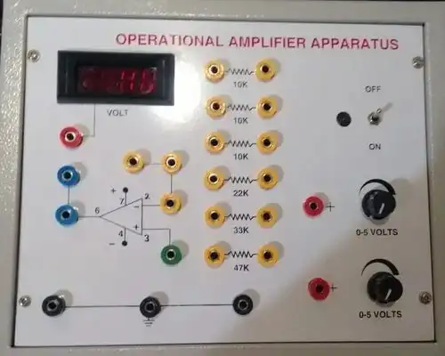
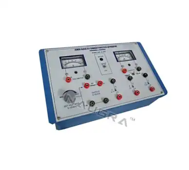
Differential amplifiers are useful in electrically noisy environments where a low amplitude electrical signal can be easily corrupted by the effect of unwanted external noise. In this scenario, a single-ended amplifier would be unsuitable since it would also amplify the unwanted noise signal as well as the desired input signal. A differential amplifier works on the principle that unwanted electrical noise couples equally onto both input terminals of the amplifier and will therefore be rejected allowing only the wanted signal to be amplified. They are used at the front end of analog systems being used to detect a low amplitude electrical signal e.g. an ECG monitor to detect heart rate where the electrical signal may be of the order of only a few millivolts. The purpose of the differential amplifier is to increase the amplitude of the heart signal to a level where it can be converted into a digital form. The gain of the circuit can be adjusted by appropriate selection of external resistors connected between the output and input terminals.
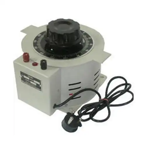
Auto-transformers definition: a single winding transformer with the primary and secondary windings magnetically and electrically connected.
So far, we have dealt with transformers that have no electrical connection between the primary and secondary winding. The only connection has been magnetic. Auto-transformers, on the other hand, do have an electrically conductive link between the primary and secondary windings. There is only one winding in an autotransformer. The common winding is the portion shared by the primary and secondary.