Power Electronics and Drives Lab focuses on the power electronics course and it deals with the practical understanding and demonstration to the students about the various power electronic techniques such as AC/DC converters, DC/DC converters, DC/AC converters, AC/AC converters and various motor drives. This lab provides the knowledge on Power Electronic Circuits and their extensive applications for the power systems industry
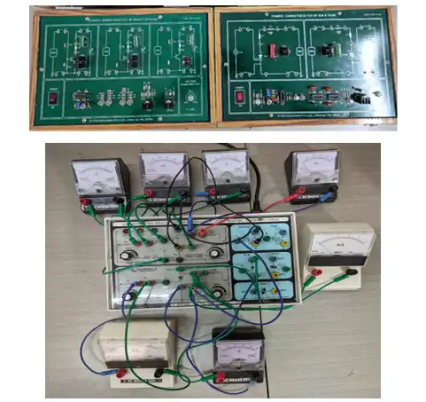
This module is used to understand the behavior of semi-conductor devices during steady state and transient conditions
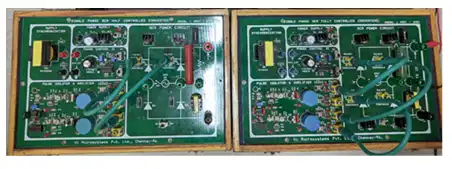
This module is used to understand the operation of single phase controlled rectifier in half and fully controlled manner. Single-phase rectifiers are used to convert AC supply voltage and current to DC, as required for powering equipment and digital electronic devices. Standard mains power supplied to homes and commerce is AC. However, most digital electronics are designed to run on DC power
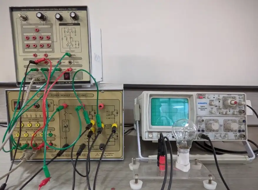
This module is used to understand the operation of single phase inverter which is mainly used for UPS applications, motor control applications
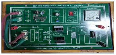
This module is used to understand the operation of ZVS / ZCS. Efficiency of converter is increased because of power devices operates under zero voltage and zero current condition
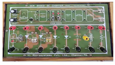
Voltage commutated chopper is one of the simplest and earliest chopper circuit. This chopper is generally used in high power circuit where load fluctuation is not very large. This chopper is also known as Parallel Capacitor Turn Off Chopper, Impulse Commutated Chopper or Classical Chopper
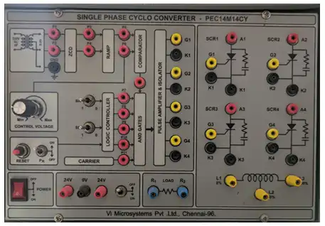
A single phase to single phase cycloconverter is a type of cycloconverter whose input and output are single phase AC. The basic function remains the same i.e. frequency changing. A single phase to single phase cycloconverter may either be mid-point type or bridge type step-up or step-down cycloconverter
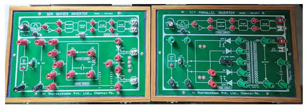
Inverter is used to convert DC voltage into AC voltage and extensively used in UPS, HVDC and motor control applications. The inverter circuit in which the commutating component C (capacitor) is connected in parallel with the load via transformer. In a series inverter, the commutating elements L and C are connected in series with the load. This constitutes a series RLC resonant circuit
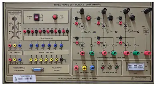
Three-phase controlled rectifiers have a wide range of applications, from small rectifiers to large high voltage direct current (HVDC) transmission systems. They are used for electrochemical processes, motor drives, traction equipment, controlled power supplies and many other applications
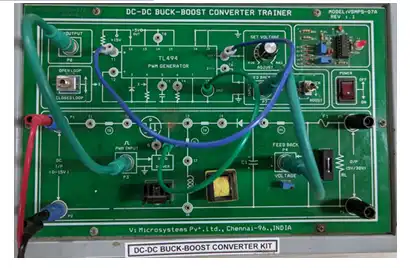
This is also known as buck-boost converter and used to increase or decrease the DC voltage levels. This module is used to understand these concepts with open and closed loop operation. DC / DC power converters are the important one for the solar PV integration with grid
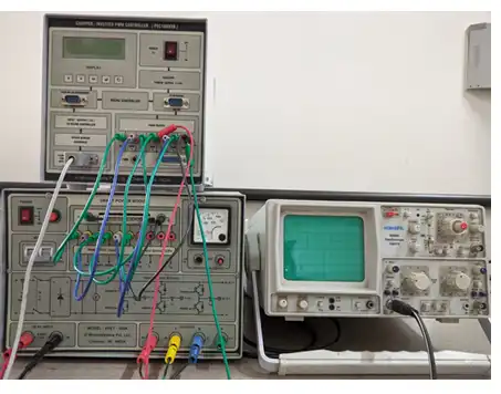
Three phase inverter converts input DC voltage into output three phase AC voltage. It is used to control the speed of AC drives, HVDC applications, UPS systems
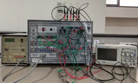
Three phase inverter converts input DC voltage into output three phase AC voltage. It is used to control the speed of AC drives, HVDC applications, UPS systems
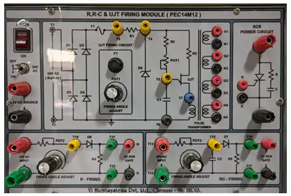
SCR firing circuits generate a single pulse or a train of pulses instead of a continuous DC gate signal. This allows precise control of the point at which the SCR is fired. In addition, it is easy to provide electrical isolation between the SCR and the gate trigger circuit
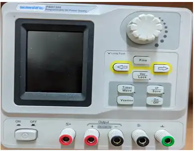
Programmable power supplies are digitally controlled power sources that provide accurate and adjustable levels of voltage, current, and frequency. They include a processor, voltage/current programming circuits, current shunt, and voltage/current read-back circuits
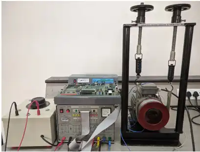
An induction motor or asynchronous motor is an AC electric motor in which the electric current in the rotor needed to produce torque is obtained by electromagnetic induction from the magnetic field of the stator winding. An induction motor can therefore be made without electrical connections to the rotor
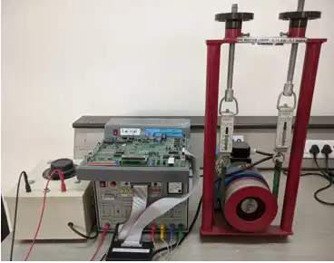
The variable voltage to the armature of a dc motor for speed control can be obtained from a dc chopper which is a single stage dc to dc conversion device. The voltage variation at the load terminals can be obtained by using either current limit control or time ratio control
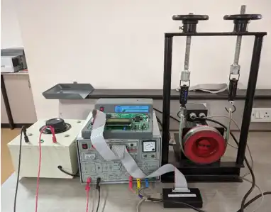
In a brushless DC motor, the relationship between the applied voltage and the load torque determines the rotational speed. This means that, when using the motor, you can control the rotational speed of the motor by changing the applied voltage. The most common way to control a BLDC motor is to use Hall sensors to determine the rotor position. The control system senses the rotor position and the proper voltage pattern is applied to the motor
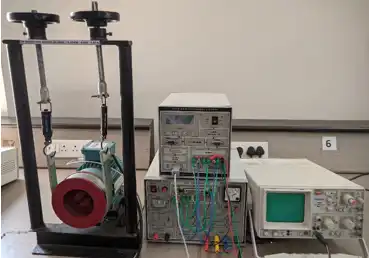
AC induction motor speed control has traditionally involved controlling the motor's input voltage and frequency through use of a three phase pulse-width-modulating (PWM) controlled-voltage inverter. This method provides a smooth speed control without affecting motor torque.
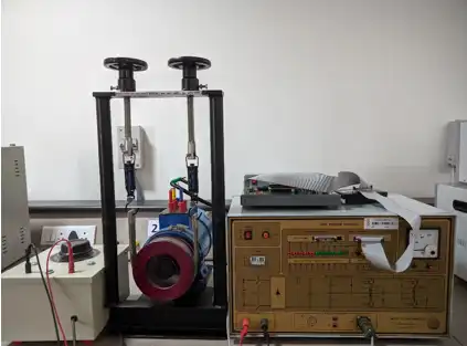
The SRM has wound field coils as in a DC motor for the stator windings. The rotor however has no magnets or coils attached. It is a solid salient-pole rotor (having projecting magnetic poles) made of soft magnetic material (often laminated steel). Switched reluctance motors are especially suitable for a variety of coal mining equipment, such as cutters, conveyors and coal ploughs